


描述
360度 旋轉編碼器模組
工作電壓:5V 一圈脈衝數:20
360度 旋轉編碼器模組 可通過旋轉可以計數正方向和反方向轉動過程中輸出脈衝的次數,旋轉計數不像電位計,這種轉動計數是沒有限制的。配合旋轉編碼器上的按鍵,可以復位到初始狀態,即從0開始計數。
工作原理:
增量編碼器是一種將旋轉位移轉換為一連串數字脈衝信號的旋轉式傳感器。這些脈衝用來控制角位移。在 Eltra 編碼器中角位移的轉換採用了光電掃描原理。讀數係統以由交替的透光窗口和不透光窗口構成的徑向分度盤(碼盤)的旋轉為依據,同時被一個紅外光源垂直照射,光把碼盤的圖像投射到接收器表面上。接收器覆蓋著一層衍射光柵,它具有和碼盤相同的窗口寬度。接收器的工作是感受光盤轉動所產生的變化,然後將光變化轉換成相應的電變化。再使低電平信號上升到較高電平,並產生沒有任何干擾的方形脈衝,這就必須用電子電路來處理。讀數係統通常採用差分方式,即將兩個波形一樣但相位差為 180 °的不同信號進行比較,以便提高輸出信號的質量和穩定性。讀數是再兩個信號的差別基礎上形成的,從而消除了乾擾。
360度 旋轉編碼器模組 / 增量編碼器:
增量編碼器給出兩相方波,它們的相位差90 °,通常稱為A 通道和B 通道。其中一個通道給出與轉速相關的信息,與此同時,通過兩個通道信號進行順序對比,得到旋轉方向的信息。還有一個特殊信號稱為Z 或零通道,該通道給出編碼器的絕對零位,此信號是一個方波與A 通道方波的中心線重合。
增量型編碼器精度取決於機械和電氣兩種因素,這些因素有:光柵分度誤差、光盤偏心、軸承偏心、電子讀數裝置引入的誤差以及光學部分的不精確性。確定編碼器精度的測量單位是電氣上的度數,編碼器精度決定了編碼器產生的脈衝分度。以下用360 °電氣度數來表示機械軸的轉動,而軸的轉動必須是一個完整的周期。要知道多少機械角度相當於電氣上的360度,可以用下列公式來計算:電氣360 =機械360 ° /n °脈衝/轉
圖:A、B換向時信號
編碼器分度誤差是以電氣角度為單位的兩個連續脈衝波的最大偏移來表示。誤差存在於任何編碼器中,這是由前述各因素引起的。Eltra編碼器的最大誤差為± 25電氣角度(在已聲明的任何條件下),相當於額定值偏移± 7%,至於相位差90 °(電氣上)的兩個通道的最大偏差為± 35電氣度數相當於額定值偏移± 10%左右。
UVW信號增量型編碼器
除了上述傳統的編碼器外,還有一些是與其它的電氣輸出信號集成在一起的增量型編碼器。與UVW信號集成的增量型編碼器就是實例,它通常應用於交流伺服電機的反饋。這些磁極信號一般出現在交流伺服電機中,UVW信號一般是通過模擬磁性原件的功能而設計的。在Eltra編碼器中,這些UVW信號是用光學方法產生,並以三個方波的形式出現,它們彼此偏移120 °。為了便於電機啟動,控制電動機用的啟動器需要這些正確的信號。這些UVW磁極脈衝可在機械軸旋轉中重複許多次,因為它們直接取決於所連接的電機磁極數,並且用於4、6或更多極電機的UVW信號。
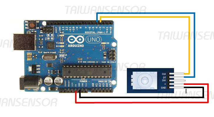
Connect Arduino 360 Degree Encoder to Arduino Uno as following :
- VCC to 5V
- GND to GND
- CLK to D3
- CLK to D4
/**************
 * VCC to 5V  *
 * GND to GND *
 * CLK to D3  *
 * CLK to D4  *
 **************/
int pinA = 3;
int pinB = 4;
int encoderPosCount = 0;
int pinALast;
int aVal;
boolean bCW;

 void setup()
 {
  //SET pinA and pinB and input
   pinMode (pinA,INPUT);
   pinMode (pinB,INPUT);
   pinALast = digitalRead(pinA);//Read Pin A
   Serial.begin (9600);
   Serial.println("BEGIN");
   Serial.println();
 }

 void loop()
 {
   aVal = digitalRead(pinA);
   if (aVal != pinALast)
   {
     if (digitalRead(pinB) != aVal) //We're Rotating Clockwise
     {
       encoderPosCount ++;
       bCW = true;
     }

     else

     {
       bCW = false;
       encoderPosCount--;
     }

     if (bCW)
     {
       Serial.println ("Rotate Clockwise");
     }

     else

     {
       Serial.println("Rotate Counterclockwise");
     }

     Serial.print("Encoder Count: ");
     Serial.println(encoderPosCount);
     Serial.println();
   }

   pinALast = aVal;
 }
360 degree rotary encoder module
100% Brand new and high quality.
Material: Electronic components + PCB
Operating voltage: 5V
Circle pulses: 20
By rotating the rotary encoder can be counted in the positive direction and the reverse direction during rotation of the output pulse frequency,
unlike rotary potentiometer counter, which species rotation counts are not limited. With the buttons on the rotary encoder can be reset to its initial state, that starts counting from 0.
incremental encoder is a displacement of the rotary pulse signal is converted to a series of digital rotary sensors. These pulses are used to control angular
displacement. In Eltra angular displacement encoder conversion using a photoelectric scanning principle. Reading system of alternating light transmitting window and the window is not consisting of radial indexing plate (code wheel) rotating basis, while being an infrared light source vertical irradiation light to the code disk image onto the receiving on the surface. Receiver is covered with a diffraction grating, which has the same code disk window width. The receiver’s job is to feel the rotation of the disc resulting changes, and change the light into corresponding electrical changes.
Then the low-level signals up to a higher level, and generates no interference square pulse, which must be processed by electronic circuits. Reading systems typically employ a differential manner,
about the same but the phase difference of the two waveforms different by 180°compared to the signal in order to improve the quality and stability of the output signal. Reading is then the difference between the two signals formed on the basis,thus eliminating the interference.


