


描述
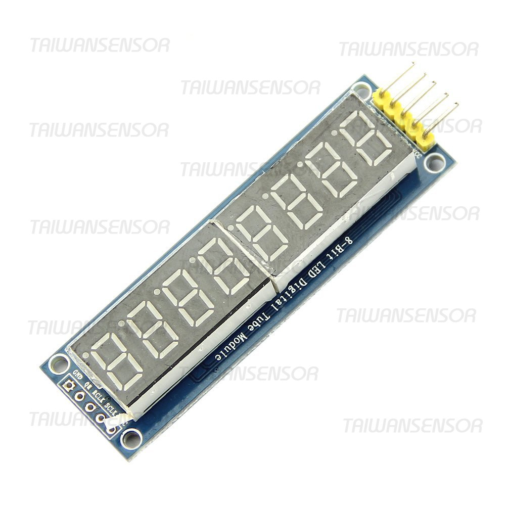
8位 七段顯示器模組 八位 串列控制 595晶片 驅動
- 採用2片595驅動數碼管,需要單片機3路IO口,根據數碼管動態掃描原理進行顯示;
- 寬工作電壓3.3V到5V;
- PCB板尺寸:71mm*22mm
- 數碼管型號:0.36 4位共陽
8 digital LED Display Module eight serial module 595 drives
- Use two 595-driven digital control, 3-way needed microcontroller IO port, according to the digital display dynamic scanning principle
- Wide Operating Voltage: 3.3V to 5V
- Digital Tube Model: 0.36 4 common anode
- PCB Plate Size: 71X22X10mm/2.79*0.86*0.39″”
Arduino 範例一
/*
  Modify from Liquid Crystal example
  For 8 x 7 segment module
*/

#define LATCH  12  //pin 12 of BBFuino connect to RCK of 8x7segment module
#define CLOCK  11  //pin 11 of BBFuino connect to SCK of 8x7segment module
#define DATA   10  //pin 10 of BBFuino connect to DIO of 8x7segment module
#define LED    13  //LED is connected to pin 13 of Arduino
#define  MultiplexDelay  1  //delay for multiplexing between digit on 8x7segment module
#define LEFT   0  // define the value for left justify
#define RIGHT  1  // define the value for right justify
#define BLANK 11  //array element to make 7segment blank


// array to activate particular digit on the 8x7segment module
// it is the common anode of 7 segment
byte anode[8] = { 0b10000000,  //digit 1 from right
                    0b01000000,  //digit 2 from right
                    0b00100000,  //digit 3 from right
                    0b00010000,  //digit 4 from right
                    0b00001000,  //digit 5 from right
                    0b00000100,  //digit 6 from right
                    0b00000010,  //digit 7 from right
                    0b00000001   //digit 8 from right
                    };

//array for decimal number, it is the cathode, please refer to the datasheet.
//therefore a logic low will activete the particular segment
                    //PGFEDCBA, segment on 7 segment, P is the dot
byte cathode[12] = {0b11000000,  // 0
                    0b11111001,  // 1
                    0b10100100,  // 2
                    0b10110000,  // 3
                    0b10011001,  // 4
                    0b10010010,  // 5
                    0b10000010,  // 6
                    0b11111000,  // 7
                    0b10000000,  // 8
                    0b10010000,  // 9
                    0b01111111,  //dot
                    0b11111111   //blank
                    };

//fucntion to send the serial data out to two 74HC595 serial to parallel shift register and activate the 7 segment.
void display8x7segment(byte datapin, byte clockpin, byte latchpin, byte digit, byte number)
{
    digitalWrite(latchpin, LOW);
    shiftOut(datapin, clockpin, MSBFIRST, digit); // clears the right display
    shiftOut(datapin, clockpin, MSBFIRST, number); // clears the left display
    digitalWrite(latchpin, HIGH);
}

//function to display value on 8x7 segment display according to the justify state
void displayNumber8x7segment(byte justify, unsigned long value)
{

   byte decimal[8] = {0};
   value = value % 100000000;  //ensure the value is within 8 digits only
   decimal[7] = value / 10000000;  //extract digit 7 from value
   value = value % 10000000;       //extract the rest of 7 digit value
   decimal[6] = value / 1000000;
   value = value % 1000000;
   decimal[5] = value / 100000;
   value = value % 100000;
   decimal[4] = value / 10000;
   value = value % 10000;
   decimal[3] = value / 1000;
   value = value % 1000;
   decimal[2] = value / 100;
   value = value % 100;
   decimal[1] = value / 10;
   decimal[0] = value % 10;
   byte zero = 0;
   if (justify == RIGHT)
   {
     for(byte e = 8; e > 0 ; e --)
     {
       if(zero == 0)
       {
         if(decimal[e-1] != 0)
         {
           display8x7segment(DATA, CLOCK, LATCH, anode[e-1], cathode[decimal[e-1]]);
           zero = 1;
         }
       }
       else display8x7segment(DATA, CLOCK, LATCH, anode[e-1], cathode[decimal[e-1]]);

     delay(MultiplexDelay);
     }
   }
   else  //if justify == left
   {
     byte d = 0;
     for(byte e = 8; e > 0; e --)
     {
       if(zero == 0)
       {
         if(decimal[e-1] != 0)
         {
           display8x7segment(DATA, CLOCK, LATCH, anode[7], cathode[decimal[e-1]]);
           zero = 1;
           d ++;
           delay(MultiplexDelay);
         }
       }
       else
       {
         display8x7segment(DATA, CLOCK, LATCH, anode[7-d], cathode[decimal[e-1]]);
         d ++;
         delay(MultiplexDelay);
       }

     }

   }
}

void setup() {
  pinMode(LATCH, OUTPUT);
  pinMode(CLOCK, OUTPUT);
  pinMode(DATA, OUTPUT);
  pinMode(LED, OUTPUT);
  digitalWrite(LATCH, HIGH);
  digitalWrite(LED, LOW);  //off LED
  // set up the LCD's number of columns and rows:

  delay(1000);  //delay for 1 second

}

void loop(){

  //1st demo, 8x7segment will display decimal value from 0 to 9 and dot from 1st digit (most right) until the last digit (most right)
  for(byte i = 0; i < 8; i++)
  {
    for(byte k = 0; k < 11; k++)
    {
       display8x7segment(DATA, CLOCK, LATCH, anode[i], cathode[k]);

       delay(300);
    }
  }
  delay(1000);  //delay 1 second

  //2nd demo, 8x7segment will display same decimal from 0 to 9 and dot across all 8 digit
  for(byte k = 0; k < 11; k++)
    {
        display8x7segment(DATA, CLOCK, LATCH, 0xff, cathode[k]);  //activate all digit

        delay(300);
    }
  delay(1000);  //delay 1 second

  //3rd demo, 8x7segment will display a decimal value increasing like normal counter.
  for (unsigned long value = 0; value < 100000000; value ++)
  {
     for(byte i = 0; i < 10 ; i ++)
      {

      displayNumber8x7segment(RIGHT, value);  //display the value in right justify format
     }
  }
  delay(1000);

}


