


描述
PCA9685 16路 12-bit PWM 控制板 16 路舵機驅動模組 機器人開發利器
台灣智能感測科技官網, 購買 更多關於 12-bit-PWM-控制板, 16路, PCA9685, Servo, 控制器, 機器人, 舵機驅動板, 舵機驅動模組, 的產品
PCA9685 16路12-bit PWM 控制板 16 路舵機驅動模組 機器人開發利器
使用一組 I2C通訊介面最多可控制16路舵機驅動模組
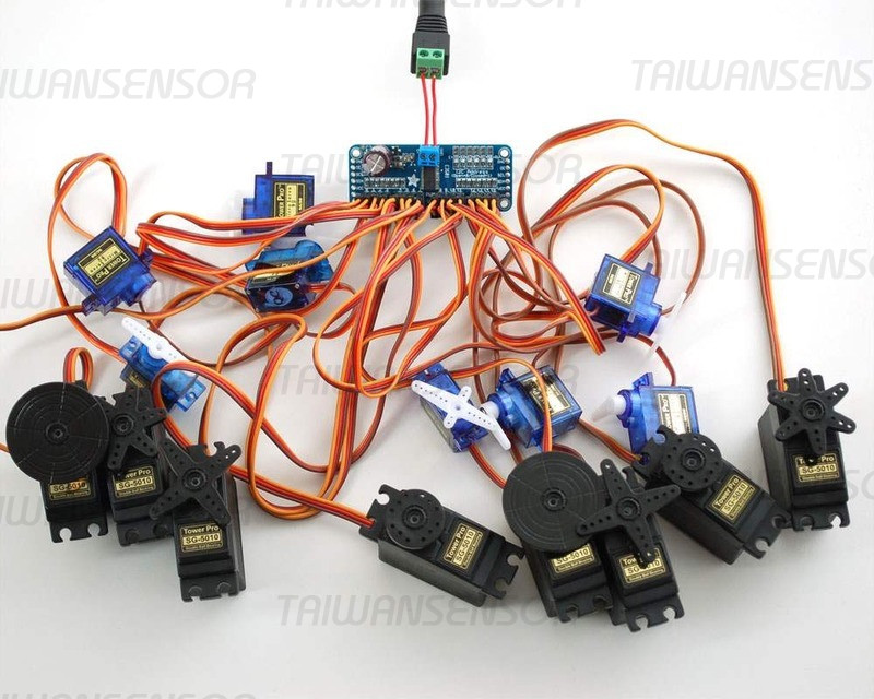
PCA9685 是一款16路舵機控制擴展板,此驅動板最多可級聯62個驅動板,總共可以驅動992個舵機,實現多自由度機械臂,六足機器人,多軸控制等應用。當你的在一個專案中,碰到了微控制晶片的PWM輸出引腳不夠用的情況,那麼這款PCA9685 16路舵機就能很快幫你解決這個問題了!只要你的主控晶片具備了I2C通信,就能夠讓主控晶片和PCA9685通信,實現多個 舵機的同時控制了。PCA9685 16路舵機控制晶片採用i2c通信,內置了PWM驅動器和一個時鐘。這和TLC5940系列有很大不同。你不需要不斷發送信號而佔用你的單片機!
PCA9685是一款16路舵機控制擴展板,此驅動板最多可級聯62個驅動板,總共可以驅動992個舵機,實現多自由度機械臂,六足機器人,多軸控制等應用。當你的在一個專案中,碰到了微控制晶片的PWM輸出引腳不夠用的情況,那麼這款PCA9685 16路舵機就能很快幫你解決這個問題了!只要你的主控晶片具備了I2C通信,就能夠讓主控晶片和PCA9685通信,實現多個 舵機的同時控制了。PCA9685 16路舵機控制晶片採用i2c通信,內置了PWM驅動器和一個時鐘。這和TLC5940系列有很大不同。你不需要不斷發送信號而佔用你的單片機!
規格參數:
- 使用PCA9685晶片
- 使用I2C介面,不佔用GPIO介面(預設位址0x40)
- 同時支持樹莓派(3.3v電平)和arduino(5v電平),但兩種主控不能同時控制
- 支援16路PWM通道輸出,可以控制16路舵機或者LED燈
- 12位元解析度,可調PWM頻率高達1.6KHz
- 所有PWM輸出線上都放一個220歐姆系列電阻器來保護他們,並能輕易的驅動LED。
- 電源輸入端子
- 綠色電源指示燈
- 接線板上輸入的反向極性保護
- 級聯設計
- V+線上放置一個大電容(在某些場合你會需要) 週邊輸入最大電壓取決於這個10V1000uf的電容
- 3P標準介面,方便連接舵機和LED燈
- 6位可調地址(A0-A5),方便級聯擴展板
應用範圍:
- RGB 或 RGBA LED 驅動器
- LED 狀態信息
- LED 顯示器
- LCD 背光
- 手機或手持設備的鍵盤背光
- 伺服馬達控制器
16 Channel PWM/Servo Driver IIC interface-PCA9685 for arduino or Raspberry pi shield module servo shield
- It is 5V compliant, which means you can control it from a 3.3V microcontroller and still safely drive up to 6V outputs (this is good for when you want to control white or blue LEDs with 3.4+ forward voltages)
- 6 address select pins so you can wire up to 62 of these on a single i2c bus, a total of 992 outputs
- Adjustable frequency PWM up to about 1.6 KHz;Configurable push-pull or open-drain outputManufacturer
- 12-bit resolution for each output – for servos, that means about 4us resolution at 60Hz update rate
An I2C-controlled PWM driver with a built in clock. That means that, unlike the TLC5940 family, you do not need to continuously send it signal tying up your microcontroller, its completely free running!
1.Output enable pin to quickly disable all the outputs
2. Terminal block for power input (or you can use the 0.1″ breakouts on the side)
3. Reverse polarity protection on the terminal block input
4. Green power-good LED
5. 3 pin connectors in groups of 4 so you can plug in 16 servos at once (Servo plugs are slightly wider than 0.1″ so you can only stack 4 next to each other on 0.1″ header
6. “Chain-able” design
7. A spot to place a big capacitor on the V+ line
8. 330 ohm series resistors on all the output lines to protect them, and to make driving LEDs trivial
9. Solder jumpers for the 6 address select pins


