


描述
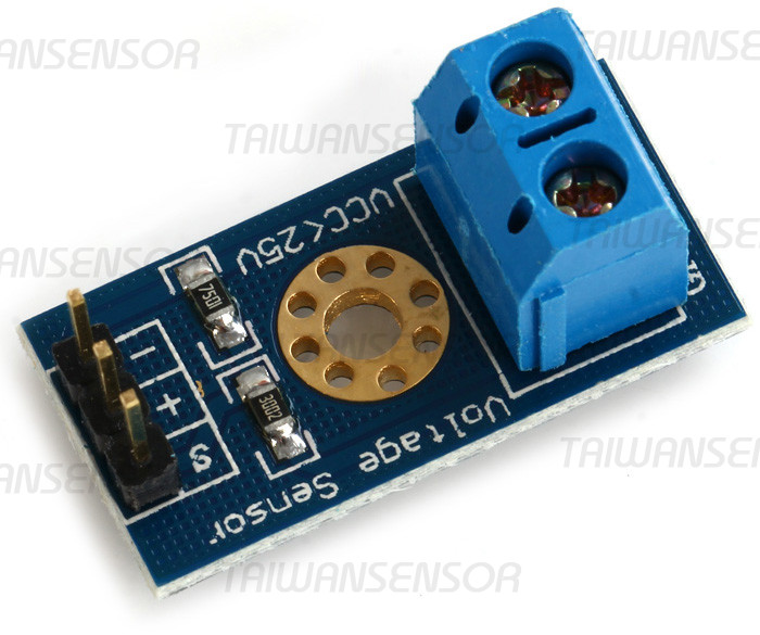
Voltage Sensor 電壓感測器 電壓檢測模組
此模組基於電阻分壓原理所設計,能使端子介面輸入的電壓縮小5倍,Arduino類比輸入電壓最大為5V,那麼電壓檢測模組的輸入電壓則不能大於5V×5=25V(如果用到3.3V系統,輸入電壓不能大於3.3Vx5=16.5V)。因為Arduino所用AVR晶片為10位元AD,所以此模組的類比解析度為0.00489V(5V/1023),故電壓檢測模組檢測輸入最小電壓為0.00489V×5=0.02445V。
- 電壓輸入範圍:DC0~25V
- 電壓檢測範圍:DC0.02445V~25V
- 電壓類比解析度:0.00489V
- DC輸入介面:端子正極接VCC,負極接GND
- 輸出介面:”+”接5/3.3V, “-“接GND,”s”接Arduino的AD引腳
#include <Wire.h>
int val11;
float val2;


void setup()
{
  Serial.begin(9600);
  Serial.println("Voltage: ");
  Serial.print("V");
}
void loop()
{
      float temp;
      val11=analogRead(1);
      temp=val11/4.092;
      val2=(temp/10);
      Serial.println(val2);


   delay(1000);
}
A simple but very useful module which uses a potential divider to reduce any input voltage by a factor of 5. This allows you to use the analogue input of a microcontroller to monitor voltages much higher than it capable of sensing.
For example with a 0V – 5V analogue input range, you are able to measure a voltage up to 25V.
This module also includes convenient screw terminals for easy and secure connection of a wire.
This module is based on a principle of resistive voltage divider design, can make the red terminal connector input voltage to 5 times smaller. Arduino analog input voltages up to 5v, the voltage detection module input voltage not greater than 5Vx5=25V (if using a 3.3V systems, input voltage not greater than 3.3Vx5=16.5V).
Arduino AVR chips have 10-bit AD, so this module simulates a resolution of 0.00489V (5V/1023), so the minimum voltage of input voltage detection module is 0.00489Vx5=0.02445V.
Specification:
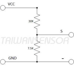
- Divider ratio: 5:1
- Resistor Tolerance: 1%
- Max input voltage: 25V
- Resistor Value: 30K/7.5K Ohm
Pinout:
INPUT:
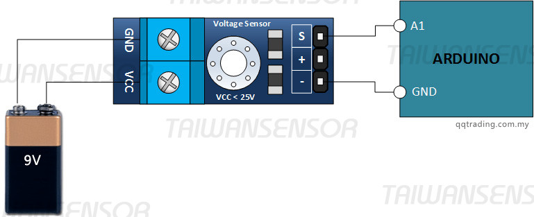
- GND – This is where you connect the low side of the voltage you are measuring. * Caution: This is the same electrical point as your Arduino ground.
- VCC – The is where you connect the high side of the voltage you are measuring (0 – 25V)
OUTPUT:
- S: This connects to your Arduino analog input.
- – (or minus): This connects to your Arduino ground.
- +: This is not connected. It does absolutely nothing.
Schematic
The schematic for this is pretty straight forward. As previously mentioned, its just a couple of resistors. In fact, you could build your own in a pinch.
Voltage Sensor Module tutorial (by HenrysBench)
The Connections
Find yourself a 9 volt battery and connect it, your voltage sensor module and Arduino as shown below.
The Sketch
Enter the following sketch, upload it and go to town. If you open your Arduino serial monitor you will be able to see the voltage.
/*
DC Voltmeter Using a Voltage Divider
Based on Code Created By
T.K.Hareendran
*/

int analogInput = A1;
float vout = 0.0;
float vin = 0.0;
float R1 = 30000.0; //
float R2 = 7500.0; //
int value = 0;
void setup(){
   pinMode(analogInput, INPUT);
   Serial.begin(9600);
   Serial.print("DC VOLTMETER");
}
void loop(){
   // read the value at analog input
   value = analogRead(analogInput);
   vout = (value * 5.0) / 1024.0; // see text
   vin = vout / (R2/(R1+R2));

Serial.print("INPUT V= ");
Serial.println(vin,2);
delay(500);
}


